
Gerald Pasdast, UCIe Consortium Form Factor & Compliance Workgroup Co-Chair and Senior Principal Engineer at Intel, along with Stefan Rusu, Senior Director at TSMC, presented a webinar earlier this year discussing standard laminate and advanced options such as silicon interposers, silicon bridges, and fan-out/RDL from multiple vendors. The presentation also explored the 2D and 2.5D physical bump map arrangements along with interoperability rules.
During the webinar – which can be found on the UCIe Consortium YouTube channel – attendees posed several questions. Below, we address questions the presenters were unable to respond to during the live webinar. If you have additional questions for UCIe representatives, please contact press@uciexpress.org.
Q: What is the range of Redistribution routing (RDL) layer count for UCIe-A when looking at x32 or 64x footprints (assuming, e.g., 2 um L/S)?
This is implementation specific and there is no limit imposed by the UCIe specification. Based on our experience, we expect most implementations will route all UCIe-A signals over two (2) to four (4) RDL routing layers, depending on the design rule specifics.
Q: Will future UCIe specifications for optical implement an optical UCIe PHY specification or will it target optimization of the electrical UCIe for EO chiplets?
The UCIe specification supports re-timers, which can support using UCIe for attaching to optical modules integrated into the package and connect off-package. At this point, there are no plans to standardize optical signaling, though that could change in the future.
Q: Can you share any proposals/solutions for testing the interconnection between dies in both the package test and wafer test?
Both wafer-level as well as post-assembly package testing details are implementation specific and are outside the scope of the UCIe specification. However, based on experience, wafer-level testing may include scan and near-end-loopback types of testing and post-packaging testing with possible far-end-loopback to testing various levels of the architecture. This includes electrical and die-to-die adapter/protocol, where applicable.
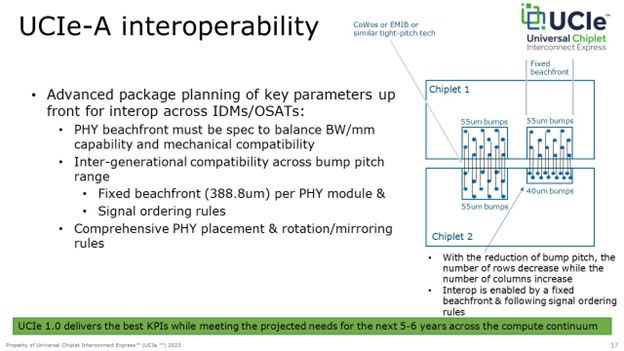
Q: One of the slides in the presentation showed different Row/Column configurations connected to each other. However, the channel length between lanes seems to vary quite a bit which could impact lane-level settings; it could be a challenge to have common calibration settings across all lanes. How is this challenge being addressed?
We have analyzed combinations of column designs, bump pitch range, and associated max data rates. Our analysis shows that for most cases, the lane-to-lane skew can be maintained within a few picoseconds (ps). With techniques such as length-matching routing design, and on-silicon lane-to-lane de-skew, we think this is a reasonable variation to ensure both performance and interoperability.
Q: Why is there a large gap between UCIe-A and UCIe-S pitch? Is there an interesting packaging technology that would target this gap?
Based on feedback from OSATs (Outsourced Semiconductor Assembly and Test), advanced packaging technologies, 55um, and tighter bump pitches are widely deployed across all the major sub-categories including silicon interposers, silicon bridges, and RDL/FO technologies. Widely available standard package bump pitches, similarly, are available at 100um and higher.
Note that standard packaging technologies are organic-based and advanced package technologies are mostly silicon-based. These two types of packaging technologies have natural optimization ranges and there is no easy way to bridge the gaps between them.
Q: The High Bandwidth Memory 3 (HBM3) spec has a 75um bump pitch. Will UCIe technology be implemented with HBM3 on the same package? If so, how will UCIe address the bump pitch of ~75um?
We expect a wide variety of usages for UCIe technology across segments. We are expecting UCIe to co-exist with HBM memory integration within the same package. In existing HBM usages, there are examples of the host die having a significantly tighter bump pitch (for example, 45um or 55um) compared to the HBM device bump pitch of 75um. If the keep-out region is maintained between the differing bump pitch regions, the depth, and diagonal pitches can be different. Using this same example, we can have UCIe-A co-exist with HBM devices in the same package, all with different bump pitches.